How to Repair an Automotive ECU Damaged by Reverse Polarity
Accidentally reversing jump-lead cables—connecting positive to negative and negative to positive—is one of the most destructive mistakes an operator can make on a modern vehicle. When a reverse jump start occurs, the vehicle's electrical system experiences an immediate polarity inversion. While older carbureted cars might escape with a blown alternator diode or a melted fusible link, modern computer-controlled vehicles suffer severe stress, frequently leaving drivers stranded with a car ECU reverse polarity damage fix scenario and a dead dashboard.
When a reverse jump start car won't start, many technicians immediately assume the Engine Control Unit (ECU) is completely fried and recommend an expensive replacement unit requiring expensive programming and key synchronization. However, with component-level diagnostics, basic bench electronics gear, and proper desoldering equipment, many ECUs can be saved.
This guide outlines the step-by-step procedure for troubleshooting, desoldering, and restoring a reverse-polarity-damaged engine computer.
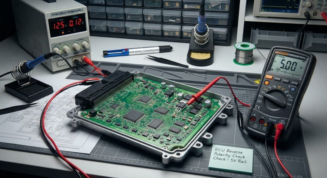
Figure 1:Bench setup for safe ECU inspection and trace analysis using a current-limited DC power supply.
Understanding Reverse Polarity Protection Mechanisms
Automotive manufacturers design Electronic Control Units with built-in sacrificial protection circuits to absorb voltage spikes and reverse connection surges. However, when sustained heavy current from a donor battery or booster pack is forced backward through the system, these protective components take the full brunt of the fault.
Typically, protection involves:
- Shunt TVS Diodes / Zener Diodes: Placed in parallel across the main 12V battery rail and ground. In a reverse polarity condition, these diodes forward-bias and act as a dead short, blowing an upstream main fuse or burning traces before delicate microcontrollers are vaporized.
- Reverse Polarity MOSFETs: Used in modern ECUs to disconnect power if the source is inverted.
- Internal Power Distribution Fuses & Fusible Links: Trace-level fuses or onboard surface-mount fuses that open up during overcurrent conditions.
Step 1: Safe Disassembly and Visual Inspection
Before applying any test equipment, open the ECU enclosure carefully. Most metal ECU housings are sealed with RTV silicone, mechanical clips, or security Torx fasteners.
- Clean the Workspace: Ensure an ESD-safe mat and grounded wrist strap are used to protect static-sensitive microprocessors.
- Remove the Cover: Gently pry open the enclosure, taking care not to gouge the multi-layer printed circuit board (PCB) or shear off surface-mount components near the edges.
- Inspect for Thermal Damage: Use a magnifying glass or stereo microscope to examine the board. Look for:
- Discolored or blackened resin around the power input section.
- Blistered or lifted copper traces.
- Cracked ceramic capacitors or exploded semiconductor packages.
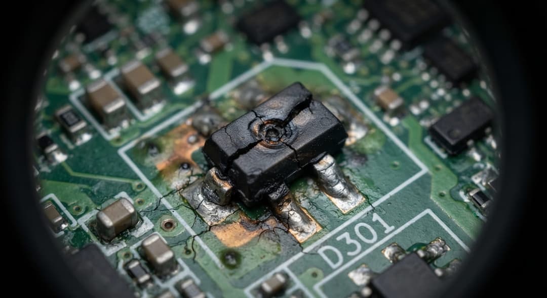
Figure 2: A sacrificed TVS clamping diode showing physical cracking and carbon residue from a severe reverse polarity surge.
Step 2: Locating and Testing Internal Protection Diodes
The primary culprit behind a blown ECU diode repair is the heavy-duty Transient Voltage Suppressor (TVS) or clamping diode situated directly behind the main power pins of the ECU connector.
- Identification: Locate the pins where battery power (12V - 14V) enters the board. Trace the tracks inward; the protection diode will typically bridge the positive rail to the ground plane.
- Multimeter Testing: Set your Digital Multimeter (DMM) to Diode Mode or Continuity Mode.
- Place the red probe on ground and the black probe on the positive rail (or across the diode terminals).
- If the meter reads 0.000 V or beeps continuously in both directions, the diode has failed into a hard short-circuit.
- This short is actually protecting the downstream logic, but it prevents the vehicle's main relay from latching, causing the entire system to stay dead.
Step 3: Desoldering and Removing Shorted Diodes
To restore power circuit functionality and test whether the short is cleared:
- Apply Flux: Apply a generous amount of no-clean rosin flux to the diode terminals.
- Thermal Management: Because ECU boards use heavy copper ground planes to dissipate heat, standard soldering irons may struggle. Use a temperature-controlled soldering station set to roughly 380°C to 400°C paired with a broad chisel tip, or utilize a hot air rework station.
- Lift the Component: Using precision tweezers, gently lift one side of the diode while heating the solder joint, then remove the component entirely.
- Post-Removal Check: Re-test the pads with your multimeter. If the short between the main power rail and ground is gone, you have successfully isolated the fault.
Note: Do not operate the vehicle without replacing this diode, as it serves as vital protection against future electrical spikes. Find a replacement component matching or exceeding the original breakdown voltage and peak pulse power rating.
Step 4: Inspecting and Repairing Burnt PCB Power Traces
If the reverse current exceeded the rating of the protection diode before a fuse could blow, copper traces on the PCB may act like fuse wire and vaporize. Fixing a fried engine computer often requires rebuilding these broken pathways.
- Trace Scraping: Use a fiberglass scratch brush or a scalpel to gently scrape away the green solder mask over the broken or blistered section of the copper trace until shiny bare copper is exposed.
- Tinning the Surface: Apply flux and a small amount of solder to the exposed copper pads.
- Wire Jumper Installation: Cut a length of enameled copper wire or stranded 22AWG hookup wire. Bridge the gap between the intact sections of the trace. Solder both ends securely.
- Mechanical Reinforcement: Secure the wire jumper to the PCB using UV-curable solder mask or structural epoxy to prevent vibration fatigue while the vehicle is running.
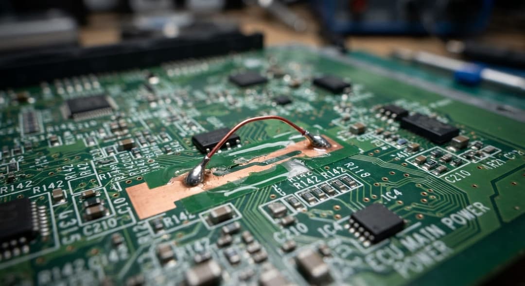
Figure 3: Professional jumper wire repair bridging a vaporized power supply trace on a multi-layer automotive PCB.
Step 5: Replacing Fried 5V Voltage Regulators
Once the main power rails are clear and traces are bridged, you must verify the low-voltage logic supply. Most automotive microcontrollers, flash memories, and sensors operate on 5V or 3.3V.
When reverse polarity occurs, step-down voltage regulators (such as linear LM2940 regulators or specialized multi-output power management ICs like Infineon or STMicroelectronics chips) frequently suffer internal breakdown, outputting full battery voltage (12V) straight into the delicate microcontroller logic pins—destroying the processor.
Diagnostic Procedure for Regulators:
- Connect a current-limited bench power supply to the ECU input pins (matching correct polarity).
- Monitor current draw. A high current draw combined with excessive heat on the regulator IC indicates an internal short.
- Check the output pin of the regulator with a multimeter. If a 5V regulator is outputting 0V or 12V, it is dead.
- Replacement: Use hot air rework to remove the damaged regulator IC, clean the pads with copper braid, and solder a genuine replacement IC onto the board.
Summary of ECU Component Faults and Remedies
| Component | Common Fault | Test Method | Remedy |
|---|---|---|---|
| Transient Voltage Suppression (TVS) Diode / Zener | Short-circuited (Low resistance / zero ohms) | Multimeter Continuity Mode / Diode Test | Desocket/Desolder and replace with matching breakdown voltage rating |
| PCB Power Trace / Copper Track | Vaporized or blistered copper trace | Visual Inspection & Continuity Test | Scrape mask, clean surface, and bridge with 22AWG copper wire jumper |
| 5V Step-Down Voltage Regulator | Internal short / Open circuit output | Voltage check across VCC and Ground under bench power | Hot-air rework and replacement with compatible linear/switching regulator IC |
| Reverse Polarity Blocking MOSFET | Gate-source junction breakdown / Drain-source short | MOSFET tester or diode drop test on pins | Replace with equivalent logic-level N-channel or P-channel MOSFET |
Final Bench Testing and Reassembly
Before installing the repaired ECU back into the vehicle:
- Current-Limited Power Test: Power the ECU on your workbench using a variable DC power supply set to current limit (e.g., 500mA). Verify that the quiescent current draw is normal and that stable 5V and 3.3V rails are present on test points.
- CAN Communication Check: If possible, hook up a logic analyzer or OBD bench harness to verify that the main processor boots up and handshakes on the CAN bus network.
- Enclosure Sealing: Apply fresh automotive-grade RTV silicone sealant around the perimeter of the aluminum housing to ensure moisture and vibration resistance upon reinstallation.
By following these diagnostic and component-level repair steps, automotive technicians can successfully salvage expensive engine control units, saving vehicle owners significant repair costs.
Would you like to consult with us regarding your auto repair needs? Contact us for a no-obligation Chat. We're here to help.
If you know already have something in mind, we might have what you're looking for, please visit Tech and Bids to search for what you need.